Create Your Own Custom Fonts Using CorelDRAW (Part I)
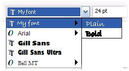 The challenge of tackling your own font design can be daunting without the right tools. Fortunately, CorelDRAW Graphics Suite has everything you need to design your own custom logotype font or typeface design.
It’s no small wonder that typing a few words gives you the ability to communicate across boundless distances in near limitless ways. We routinely email, digitally publish, post online, blog, and text with one another. This communication hinges on the existence of digital fonts you see and use every day. In fact, someone somewhere designed the font you’re reading right now.
It isn’t difficult to create a digital font. The tricky work is in the planning and construction of the letter shapes and how extensive or complex the font character set is. CorelDRAW users have long enjoyed tools and options for creating character and symbol font designs. You have everything you need to create, edit, and export your own custom digital fonts.
In this two-part tutorial, I’ll explore how you can benefit from creating your own font. I’ll cover font design considerations, available tools you can use in CorelDRAW, and best practices. You’ll also learn how to prepare and export your characters to a font file you can install and use on your system.
Although the instructions, step sequences, illustrations, and resource files provided with this tutorial were created using CorelDRAW X3, generally any CorelDRAW version (all the way back to version 3) can be used to create letter shapes and export font files.
Benefits of Designing Custom Fonts
Designing your own typeface is a creative endeavor that can yield significant rewards. Whether you’re creating a symbol font comprised of only graphic images, designing a set of custom icons for a unique use, or customizing a proprietary logo font for creating quick corporate documents, the effort is an investment that will pay dividends over time. Here are a few of the potential benefits:
- Create a unique font for a specific use Create a new elite custom font for a specific product or corporate identification package for an exclusive design project that no one else has used before.
- Create a custom logotype font Design a custom logotype font that includes corporate logos, proprietary graphics or icons, or specialized symbols to save time and money. Avoid the need to copy and paste logos into corporate documents by creating and installing a custom logotype font in corporate network environments.
- Copyright and sell your font If your font design is a hit, you may wish to license it or sell it to others and turn your creative design talents into fame and fortune.
Deciding on a Font Design Style
If you’re planning on designing your own typeface it’ll certainly help you to have at least some basic typeface design knowledge. Creating a proper typeface design is an art form unto itself and there are designers who pride themselves on their type design knowledge. Some typefaces are designed specifically for use in headline applications, while others are designed to be used primarily as body text. Of course, few fonts come equipped with a rule book, so the designer’s original intent is largely a moot point.
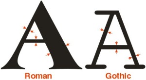
Most fonts fall into one of two basic typeface classes-Roman or Gothic. Roman typefaces are designed for headline applications and typically include vertical and horizontal character strokes that feature different widths. Gothic typefaces are designed for use as body text and usually feature consistent character strokes. The illustration below highlights the main differences between Roman and Gothic typefaces.
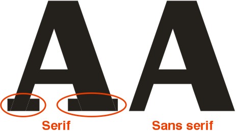
The presence of tails or serifs on letterforms is another characteristic in typeface design that differentiates one style from another. Serifs were originally introduced to increase legibility and compensate for degraded printing processes that no longer exist today. Serifs do nonetheless add a certain degree of elegance and decorative quality to type and remain in wide use. The illustration below shows examples of both serif and sans serif (meaning no serifs) character designs.
Exploring Font Anatomy
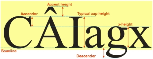
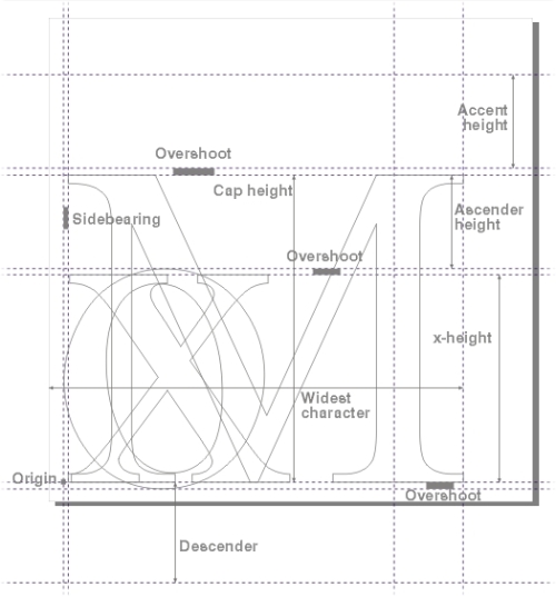
Most fonts have their own unique style largely determined by the shape, structure, and form of each of the font letters. In the typographic world, this is referred to as the letterform of the typeface. The size, construction and internal proportions of the characters all play a role in the impact and readability of the typeface. The diagram below identifies physical characteristics at play in typeface design and the list that follows describes their typographic purpose.
- Character height Vertical measure that encompasses the total character height from below the descender to above the accent height.
- Cap height Height measurement between the baseline and the top of a typical uppercase character.
- X-Height Vertical measure of a lowercase x character measured from the baseline.
- Baseline Invisible horizontal line on which all characters appear to rest and align.
- Descender Portion of a lowercase letter that extends below the baseline.
- Ascender Character portion that extends above the x-height.
- Accent height Vertical measure that encompasses the accent portion applied to an uppercase letterform.
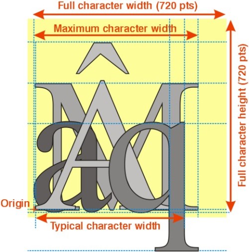
Typefaces also incorporate reference points that determine relative character position and size. This includes the origin point for each character, the maximum horizontal width, the typical character width, and the maximum vertical height. The illustration below highlights these critical reference points.
Character origin Lower-left point at which typical characters in the typeface align to.
Maximum character height Maximum vertical measure of the largest character including all accent shapes.
Typical character width For design reference only and indicates the typical width of an average character for alignment purposes.
Maximum character width Maximum width that any character in the set can occupy.
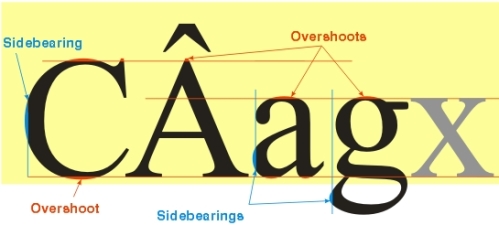
Certain letterforms are aligned vertically and horizontally to compensate for the visual distortion caused by their inherent curvature. Rounded characters (such as O, C, D and so on) and characters with extended serifs are designed to extend above, below, left and right of the points at which typical characters align. Vertical extensions are referred to as overshoots, while horizontal extensions are referred to as sidebearings. Typical character overshoots and sidebearings are shown in the illustration below.
Overshoot Extra vertical portion typically added to rounded characters or serifs that extend above the x-height or below the baseline.
Sidebearing Extra horizontal portion typically added to the left or right edges of rounded or serif characters.
CorelDRAW Font Design Tips
If you’re tackling your own complete or partial typeface design, keep in mind these essential guidelines to ensure your final design withstands the test of time. The following points should get you started on the right path:
- Create One Design For All Sizes Unlike early digital font technology where each point size was a unique font, you only need to create one font size for your design to be available in all sizes. Create your character design at a size of 720 points. There are two reasons for this. First, working at this size will enable you to easily spot any line work errors. Second (and most important), your final design will automatically match the requirements called for by CorelDRAW’s font export filter.
- Maintain a Consistent Character Thickness Be certain to create the vertical, horizontal, and angled strokes in your typeface design using a consistent thickness.
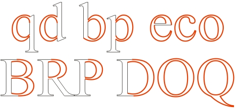
- Maintain Curve Shapes If your typeface design features rounded contours, be sure to maintain a consistent curvature across all similarly rounded characters (as shown in the samples below).
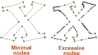
- Simplify Object Nodes Keep an eye out for excessive or redundant nodes on the shapes of your characters. A straight path need only include two nodes, and simple curves often require only two to three nodes. Keeping your characters node-simple will ensure the font is easily displayed and printed at any size. The illustration shown below highlights the optimum way to simplify a letterform.
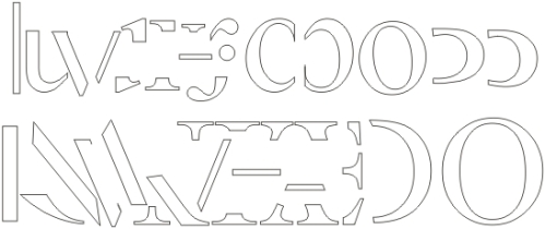
- Re-use Common Font Forms Create and copy letterform parts for use across similarly shaped character forms. This includes character curvature and serif shapes as well as vertical, horizontal, and angled strokes (see below).
Essential Font Design Tools
When it comes to creating vector font shapes, CorelDRAW is an excellent resource. CorelDRAW includes everything you need to create, modify, transform, and/or manipulate your typeface letterforms and export the final shapes into a cohesive font.
Before you begin, you should be at ease working with basic line-drawing tools and be familiar with CorelDRAW’s node-editing tools, the Shape Tool and related path and node commands, as well as various shaping commands. As you prepare to create your character shapes, consider these guidelines:
- Establish a Template Create a template with master guidelines placed at key points to ensure consistent character origin, placement, sizing, proportions, and spacing. Download this font design template (shown below) originally set up for a font similar to Times New Roman to use as the basis for your own design.
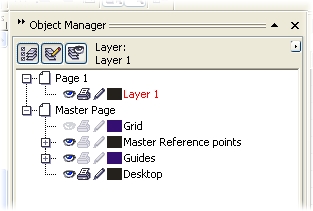
If you are creating your own font design template, set your unit page measure to points. Use the Object Manager to create a new master layer on the master page layer, place your reference marks on this page, and lock these objects in place using the Arrange > Lock Object command. Place your guidelines on the Master Page Guides layer and make both of these layers non-printing and non editable (see below).
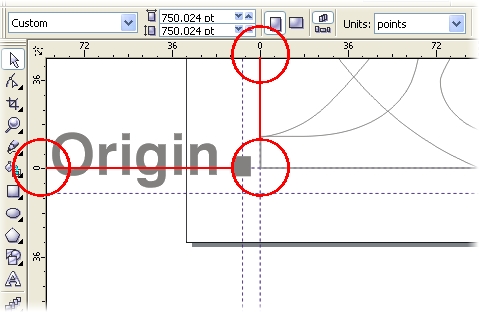
- Match Your Page Origin to your Character position Dragging your Ruler Zero origin to align with the bottom left corner of your character position at the baseline will set the zero origin of the printable page to the lower left corner of your characters. This will be a requirement when exporting the characters using CorelDRAW’s font export filter later on.
- Use Multi-Page Drawing Files to Store Character Sets Create character sets in a single CorelDRAW document using multiple pages. This way you can create complete character sets in a 100-page CorelDRAW file with each page storing a single character. Label each page using its character name for easy navigation (as shown below).

- Weld Together Common Form Shapes Use the Weld shaping command to combine multiple object shapes and create completed character composites.
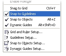
- Use Guidelines, Dynamic Guides and Snap to Guides Activating the Snap to Guidelines, Dynamic Guides, and/or Snap to Objects features in CorelDRAW (as shown below) will enable you to more easily align drawing tool cursors as you draw your letterforms.
- Combine Separate Paths Use the Combine (Ctrl+L) command to assemble two or more subpaths into a single object.
- Use Contour Effects for Design Variations Use contour effects applied using the Interactive Contour Tool to create variations on character weights. Apply subtle Outside contour effect offsets to create bolder versions and Inside contour effects for lighter versions (see below).

If you’ve never contemplated using CorelDRAW’s font building tools, this tutorial has covered many of the design and build steps you’ll need to perform in advance of creating the actual digital font file. In Part 2, I’ll cover how to export your character designs as text, logo fonts, and/or symbols for use as a resource in any application.


Managing Shadow Printing in Older CorelDRAW Releases
New Rules for the Pick Tool
Let’s start with the Pick Tool’s node tracking behavior. With the release of version 12, the default Pick Tool settings were changed to allow smoother operation of the new dynamic guides and object snapping features. Dynamic guides largely eliminate the guesswork involved in precision drawing. As you move objects or draw new ones, dynamic guides appear on-screen temporarily between your cursor and the active-object snap points on nearby objects. Your cursor magnetically follows the path of any guide that appears. Distances, angles, and alignments with other snap points make precise cursor placement quite literally a snap.
Whether you’re a new CorelDRAW user or an expert, a little refresher on nodes, node tracking, and the tools involved will help you grasp the issue more completely.
Next, let’s look at the Pick Tool and node tracking. The Pick Tool’s primary function is to enable you to select, move, transform, or rotate one or more objects. Although the function is now disabled by default, its node-tracking abilities enable it to mimic the Shape Tool in limited ways. When you enable node tracking, the Pick Tool cursor changes to the Shape Tool as you hold it over a node (see below). This cursor action (referred to as “tracking”) provides a convenient way for you to select and move any kind of node on an object without changing tools.
You can easily reactivate node tracking, but there’s a downside to consider. While enabled, node tracking is sometimes more hindrance than help – particularly if you plan to take full advantage of the new dynamic guides and object snapping in CorelDRAW 12. Here’s what it boils down to. For many users, object nodes often serve as the grab point for moving and snapping one object to the nodes on another object. When object nodes are tracked by the Pick Tool cursor, you cannot move an object by using the nodes themselves. The tracking action essentially prevents you from selecting and moving the entire object (see below).
If you’re a devotee of node tracking, here are two solutions you can use.
Keep in mind that you can always open the dialog again and disable node tracking if it is interfering with your object-snapping actions, or if you find that the display of the dynamic guides isn’t as smooth as it could be.
Drag the Tracking option button directly from the list onto the property bar. When you reach the Property Bar, an I-beam cursor appears, indicating the button’s new position. When you release the mouse button, the option button appears (see below).
Get the Most from CorelDRAW’s Enhanced Display
Assembling Panoramas in PHOTO-PAINT
ing Depth-of-Field Effects in Corel PHOTO-PAINT
Custom Sprayers Can Add Real Drawing Power
How to Crop Bitmaps in CorelDRAW
Create Cool 3D Chiseled Graphics (part 2)
It goes without saying that the shapes you’ll want to apply the chisel effect to won’t always be simple circles, squares or polygons. In fact, you can apply this effect to almost any object type you can create in CorelDRAW. But, how you approach each challenge will depend on the object type. Let’s take a close look at three uniquely different examples and explore how chiseled sides can be created.
First, we’ll see how our chisel effect can be applied to a simple open curved path. The basic thrust of this technique involves drawing an open path, applying a heavy line weight, converting the outline to an object, and applying the chisel to the resulting shape.
Creating chiseled text effects is of the more practical applications. Simple text characters are relatively easy to work with, but you’ll need to analyze each character shape before you begin. In the case of characters, the one-step Blend usually serves as the best technique to use. Let’s examine how to apply this effect to a simple sans-serif character shape.
Although nearly every example we’ve looked at shows a finished a color version, we still need to explore some basic techniques for applying color and shading. After your shapes have been created, this effect would be nothing without it. Before you begin applying color though, you’ll need to determine a few key characteristics. For example, is your chiseling recessed or on a raised surface. From which direction will it be lit? How bright is the light source? What is will the color scheme be? Your answers will help you determine which colors to use and where to place them.
Create Cool 3D Chiseled Graphics (part 1)
Before you begin the exercises to follow, it’ll help immensely for you to ensure a few invaluable snap settings are selected in CorelDRAW. You’ll need to check that certain Snap options are active using the Options dialog. To get set up, follow these steps:
You may not always need to create a negative and a positive shape for the chisel effect. In some instances, you might simply need to create the effect of a complete shape carved onto (or into) a surface. In this exercise, there is no need for the blend step, but there is certainly more emphasis on node editing and drawing. Let’s take a simple polygon as the example and create a chiseled star shape:
Fixing Sunny Day Shadows and Color Casts with Corel PHOTO-PAINT®
When bright light reflects off surfaces like snow or water, it can create highlights intense enough to cause the rest of the image to appear dull. One strategy for lightening the image is to use one of the adjustment filters in Corel PHOTO-PAINT. You can control the sliders in the Brightness/Contrast/Intensity dialog (see below), which you open by choosing Image > Adjust > Brightness/Contrast/Intensity, or by using the Ctrl+B shortcut.
If your shadows are simply isolated instances, applying an adjustment filter to the entire image may correct the shadows, but it may ruin the lighting in the rest of the image. Here’s where you need a strategy with a little more finesse to correct the image. The Effect Tool in Corel PHOTO-PAINT includes two brushes that are perfect for lightening shadowy areas interactively: Brighten and Dodge/Burn.
Brighten is the default brush type for the Effect Tool’s Brightness brush and enables you to brighten certain areas of an image interactively. You can also choose one of seven other preset brush types that vary in nib shape and size (see below). To correct image shadows, you’ll need to use a brush with a soft feathered shape at a size which roughly fits your shadow area. The Shape and Size options offer further control.
The Dodge/Burn brush is a shadow-correcting tool that enables you to brighten areas selectively based on their tone. The brush actions are fashioned after the darkroom methods used to expose film negatives onto photographic print paper. When an exposed area is dodged, less of the image is exposed onto the print paper, making the area appear lighter. Burning has the opposite effect: exposing certain areas longer makes them appear darker.
The Effect Tool in Corel PHOTO-PAINT can be incredibly handy if you’re an experienced user. But if you don’t yet have practical experience using them, here are a few tricks you can use to as you perfect your technique.
One of the drawbacks of taking photos outdoors is that a color cast often appears throughout your picture. Although color casts come in many different hues and shades, the most common is caused by a clear blue sky. The blue cast this causes alters even the true appearance of other colors in your photo, which makes this side effect particularly nasty.
The Art of Paper Folding
Five Top Photo Fixes using Corel PHOTO-PAINT
Red eye is the red glow most often seen in photos taken using an in-camera flash where the subject is directly facing the camera lens. The bright flash illuminates blood vessels at the back of the eye with ghoulish results. The problem is so unsavory that there are literally dozens of digital techniques to eliminate it. Thankfully, Corel PHOTO-PAINT has an elegant solution using a dedicated tool. You’ll find it in the Toolbox with the Clone Tool and the Touch-up Brush.
Although you likely won’t see these in digital photos, you may notice after scanning your photos that they include tiny white or dark colored specks. This may mean that you’ve inadvertently recorded minuscule particles along with your photos. You can always clean the scanner and re-scan your photos, but you just end up with a less dusty photo. You may be faced with fixing the next most common problem – removing dust and lint.
If your photo appears grainy or blotchy, it may be suffering from noise or over-compression, although each is caused by different phenomena. Noise is most often caused by low light exposures and/or using high-speed film. Over-compression, which results in degraded image quality is most often caused by applying too much compression when saving images in JPEG format. Below are examples of noise and over-compression.
Having nice, sharp photo elements is probably the most sought-after characteristic in any photo project. If your pictures look fuzzy or out of focus for whatever reason, there are several quick ways you can improve their appearance using Corel PHOTO-PAINT, but Tune Sharpen dialog (shown below) is perhaps your best choice. To open the dialog, choose Image > Correction > Tune Sharpen.
Everything you see with your eyes features a distortion effect caused by your perspective. Simple perspective distortion causes distant objects to appear smaller than the ones closer to you. Your brain can compensate for what your eyes see, but unfortunately most cameras don’t. This means photos of tall buildings or other large objects will include perspective distortion.
How to Design Better Newsletter Layouts in CorelDRAW
Creating a new layout can be a fairly intimidating experience if you’re not quite sure where to start, what your document should look like, or how you should tackle it. Even the most experienced layout artists establish a game plan before starting any layout project. If you create a layout plan and follow it one step at a time, even the most complex layouts can be relatively painless.
It is helpful to consider how your publication text will make its way onto your layout pages. Will you type it into CorelDRAW, or will it be imported from another application? If necessary, you can type text directly into your CorelDRAW layout by using the Text Tool. For large amounts of text, your best strategy is to use the resizable Edit Text dialog (see below). Once you’ve created a paragraph text frame with the Text Tool, you can open the Edit Text dialog by choosing Text > Edit Text.
With your layout plan etched on paper, your next step is to create the rough shell for your text content in CorelDRAW. Begin a new file, and set the page size, orientation, and number of pages according to your needs. If you’re accustomed to specifying measured values in printers’ measures, use the Drawing Units setting on the Property Bar to set your unit measure to “picas, points” as shown below. If you’ve never worked with printers’ measures, it may help you to know that there are roughly 6 picas to an inch and 12 points in a pica.
Unless your publication is required reading for your audience, only a fraction will have the patience to stand reading large amounts of text without craving some visual variety. Adding line rules and boxes is a simple way to organize and structure your content so that readers can follow along.
Applying a CorelDRAW text wrap effect to simple shapes is an easy way to create an interesting flow of paragraph text. The simpler the shape, the less distracting the text wrap will be. The example below shows a typical text wrap around a simple shape.
Another way to add graphic appeal is to apply a drop cap effect to the first paragraph in a story. Drop caps are applied by using the controls on the Effects page of the Format Text dialog, which you can access by clicking the Effects tab. These settings let you apply automated effects by line depth and character spacing. Just remember – only the first paragraph of a story needs a drop cap, as in the example below.
One common result of hastily prepared layouts is that uninteresting walls of gray text fill your pages. Although such layouts may be fine for epic novels, you need to create something more ambitious if you want your flyers, brochures, or newsletters to successfully attract your audience.
Creating your layout is easier if you have some optional items ready to help stretch the text or fill a space. Pull quotes and sidebars can help provide this flexibility. Pull quotes are essentially text extracts from the main story that highlight an idea. Sidebars contain text related to the main story and can be placed near the related subject but away from the main flow of the story.
Create Transparent Stylized Buttons using CorelDRAW
Glass effects are influenced by such key factors as lighting direction, light intensity, reflection, focus, and color. In any solid transparent object, the color is darker at the outer edges than in the middle. Soft overhead lighting bounces off the shiny surface of the glass, creating a reflection of the light source. The more focused the reflection, the smoother the surface will be.
The same basic effect can be used to simulate the cool 3D appearance of glass pill-shaped buttons. The steps involve rounding the corners of a rectangle filled with a specific linear fountain fill and applying resized white copies of the rectangle with transparency to simulate the reflection. Although there are several ways to construct glass pill-shaped buttons, this method is perhaps the quickest and uses the fewest shapes:
To make the button interactive, you can add a realistic rollover effect. Because you’re simulating the effect of three-dimensional objects with realistic lighting, adding shadows is the next logical step. In these next steps, we’ll use the Internet Toolbar to convert the button to a rollover and edit the button states.
Draw 3 Lighting Details using CorelDRAW